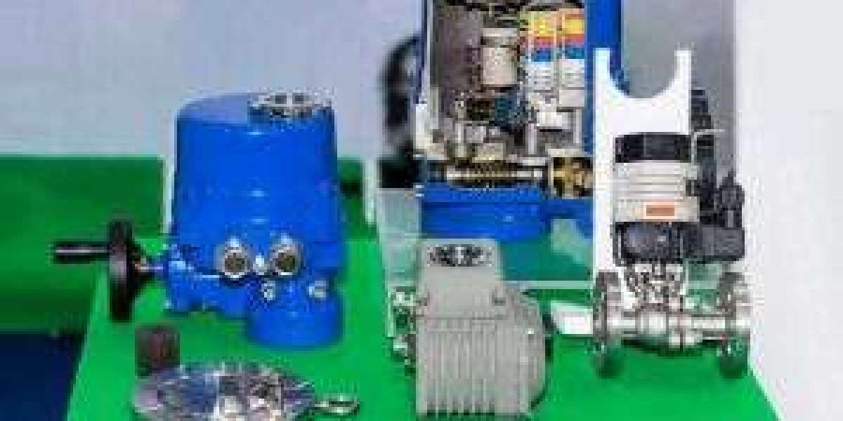
As a Leading Control Valve Manufacturer in China, We Deliver Premium Valves and Control Actuators Customized to Meet a Wide Range of Industrial Requirements.
In modern industrial systems, control valves are essential for regulating flow, pressure, and temperature. Their performance directly impacts the safety, efficiency, and reliability of a process. However, with prolonged use, valves can drift from their calibrated settings—particularly in terms of stroke accuracy—causing them to fail to open or close to the exact required position. Left unchecked, these deviations can lead to process instability, energy waste, and even system failure.
Understanding Stroke Inaccuracy
The stroke of a control valve refers to the movement of the valve plug or disc from fully closed (0%) to fully open (100%). Over time, factors like mechanical wear, vibration, environmental exposure, and pressure fluctuations can cause misalignment between the control signal and the actual valve position. As a result, a control signal intended to open the valve to 25% or 75% may yield inconsistent or incorrect valve movement.
Maintaining stroke accuracy requires regular inspection and calibration—especially in systems where precise control is critical.
Key Calibration Reference Points: 0%, 25%, 50%, 75%, 100%
Technicians calibrate valves at five standard stroke positions: 0%, 25%, 50%, 75%, and 100%. This ensures the valve responds proportionally to varying control signals. Accurate calibration across these points helps maintain linear valve performance and improves process reliability.
Calibration is particularly important for mechanical valve positioners, which require manual adjustment of two internal components:
Zero adjustment (for the 0% position)
Span adjustment (for the full stroke range)
Let’s walk through the calibration process using an air-to-open control valve as an example.
Step-by-Step Calibration Procedure for a Mechanical Valve Positioner
1. Zero Point Adjustment (4 mA Signal)
Begin by sending a 4 mA signal, which should fully close the air-to-open valve. If the valve remains even slightly open, manually adjust the zero setting on the positioner until the valve is completely closed at this baseline signal.
2. Mid-Stroke Calibration (12 mA Signal)
Next, apply a 12 mA signal to target a 50% valve opening. If the valve does not reach this midpoint accurately, adjust the span control. Ensure that the feedback arm or linkage is vertically aligned to prevent mechanical bias.
3. Full Stroke Verification (20 mA Signal)
Then, send a 20 mA signal to confirm that the valve reaches full open (100%). If the valve falls short or overshoots, further span tuning may be required.
4. Intermediate Checks (25% and 75%)
After setting the main calibration points, test the valve at 25% and 75% openings to ensure smooth, linear behavior across the full stroke. Multiple iterations may be needed to fine-tune performance.
Mechanical vs. Intelligent Valve Positioners
Mechanical Valve Positioners
These are widely used in cost-sensitive or rugged environments. They use cams, springs, and linkages to adjust valve position in response to control signals. While durable, they demand hands-on calibration and regular maintenance. For new technicians, they offer an excellent learning platform for understanding valve mechanics and control principles.
Intelligent (Digital) Valve Positioners
Modern digital positioners come equipped with microprocessors, auto-calibration, and diagnostic functions. They detect stroke endpoints automatically, adjust zero/span with minimal input, and often include a digital display or remote interface. These features reduce setup time and improve precision but still require trained personnel to interpret diagnostics and handle exceptions.
The Role of Valve Positioners in Automation
Valve positioners—whether mechanical or intelligent—are the critical interface between the control signal (typically 4–20 mA) and the valve actuator. Without a functioning positioner, the valve cannot accurately interpret commands from the control system.
Failure of a positioner due to wear, electrical faults, or misalignment can disrupt automated control loops. In high-risk industries like oil & gas, power, or chemicals, such failures can trigger costly shutdowns or pose safety risks.
Maintenance and Best Practices
To maintain stroke accuracy and positioner performance:
Schedule Regular Calibrations
Perform recalibration every 6–12 months, depending on usage and environment.Inspect Mechanical Linkages
Ensure feedback arms and rods remain aligned to avoid non-linear motion.Avoid Over-Tightening
When reassembling, avoid excessive torque that can warp cams or springs.Leverage Diagnostics
For intelligent units, use built-in diagnostic tools to detect friction, hysteresis, or sticking.Keep Records
Document calibration data to track performance trends and streamline future troubleshooting.
Final Thoughts
Control valve calibration is vital to ensuring process accuracy, energy efficiency, and operational safety. While intelligent positioners offer convenience and precision, mechanical versions still play a key role in many industries and provide a valuable hands-on training experience.
Ultimately, the effectiveness of any control loop hinges on the accuracy of valve movement. By maintaining proper calibration, understanding the tools involved, and choosing the right type of positioner for your application, you ensure smoother operations, reduced downtime, and more reliable process control.
Know more about Google SEO Directory


